Fuzzy PID Control of a 6-DOF Parallel robot
In this report, you will learn about the Fuzzy PID Control of a 6-DOF Parallel robot. So, if you are interested in learning about the control of parallel robots, keep reading.
Note: The contributors of this project are Madi Babaiasl, Seyyed Hamed Mahdioun, Askar Azizi, and Mehdi Dehghani
Abstract
Because of the sophisticated structure, parallel manipulators -unlike serial ones- have special characteristics that make them suitable for the tasks in which higher speed and acceleration with precision are required.
Identifying the real geometrical parameters in the kinematic structure of a parallel robot (calibration) and simple and accurate Control method are two crucial problems in industrial robot fabrication and manufacturing.
Among parallel structures, Hexa robot is a 6-DOF manipulator which is able to perform complex motions in the space.
In this project, based on the vision based calibrated robot parameters, a fuzzy PID controller is implemented in 6-DOF parallel robot.
This type of control contains a lot of advantages and can deal with nonlinear systems in spite of PID control problems. After successful calibration and addition of an appropriate control scheme, the robot has been considered as a color-painting prototype robot to serve in relevant industries.
Experimental tests show the advantage of fuzzy-PID control based on calibrated parameters in Hexa parallel robot.
Keywords : Parallel robots; Mechatronics; Calibration; Vision; Fuzzy PID Control.
Introduction
Today’s Robots are the inseparable part of industries and have incredible dexterity to match their brute strength, and can actually learn on the job.
While different kinds of robots i.e. serial ones or mobile robots have been designed and manufactured in industries, parallel ones are still being studied as a new candidate to compromise deficiencies of serial ones.
A manipulator whose base and end-effector (or fixed and moving platforms) are connected through a number of kinematic chains is called parallel [1].
Parallel robots have special characteristics that make them suitable for the cases in which higher speed and acceleration with higher precision are needed [1]. Moreover, since the parallel manipulator’s structure distributes the load among all limbs, they can move heavier payloads compared with serial manipulators of the same weight [1].
Positioning errors in serial kinematic chains tend to propagate additively throughout the chain links, but in parallel robots, links are not connected together serially, therefore error in parallel manipulators is averaged instead of accumulated error as in serial robots [2].
The idea of industrial parallel robots’ design was first introduced in 1947 when D. Stewart, [3], constructed a flight simulator based on his parallel model [4].
Since then, other types of parallel manipulators have been designed [5]. Hexa parallel robot, a 6-DOF parallel manipulator was introduced by F. Pierrot in 1991 [6]. The base of the Hexa robot is usually fixed to the ceiling and six motors are mounted on it. It is the use of base-mounted actuators and low-mass links that allow the mobile platform to achieve high speeds and accelerations [7].
Another model of 6-DOF parallel robot was made in Tohoku University of Japan in 1992 [8]. They first calibrated, [9], and then controlled robot [10]. A new model was made in 2005 in Germany, at Technical University of Braunschweig [11]. They used universal joints between robot links which enabled them to install encoders on passive joints for calibration purpose [12], [13].
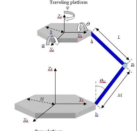
In 2014, a Hexa parallel robot was fabricated and calibrated in Robotics Lab. of School of Mechanical Engineering at Shiraz University in Iran [14] (Fig. 1). The dynamic model of the robot was studied using Lagrangian method [15] and neural networks was used to find the solution for forward kinematics of parallel robots [16], also wavenet ( wavelet neural network) was utilized as the basis of the training process [17].
Calibration process of the robot has been carried out by choosing an image processing method in which the end-effector’s position and orientation were calculated from captured frames of a chess-board paper installed on the end-effector [18]. The experimental tests of this project are carried out by this robot.
After the adequate calibration, the main problem is robot’s control method. In spite of the huge number of different research proposed, most industrial control systems are based on conventional PID (Proportional-Integral-Derivative) regulators because this controller is robust, flexible and simple to design [19].
Most of the classical industrial controllers have been provided with special procedures to automate the adjustment of their parameters (tuning and self-tuning).
However, PID controllers cannot provide a general solution to all control problems. When the process becomes too complex to describe by analytical models (time-variant, delays and non-linearity, and often with poorly defined dynamics.), it is impossible to be efficiently controlled by conventional approaches.
In this case a classical control methodology simplify the plant model in many cases, but it does not provide good performance. Therefore, an operator is still needed to control the plant.
In addition, PID controllers are often not properly tuned and there is a requirement to develop methods to automatic tuning of PID controllers.
While there exist many conventional tuning methods (hand tuning, Ziegler-Nichols tuning, TLC tuning, analytical method, by optimization or pole placement to achieving the effective control and etc.), the design of fuzzy PID controller was introduced.
This controller includes two parts: conventional PID controller and fuzzy logic control (FLC) part. The main advantage of such a controller is self-tuning the proportional, integral and derivate (KP, KI, KD) gains with the output of the system [19].
The main idea of fuzzy logic control (FLC) was introduced by Zadeh [1], and first applied by Mamdani [20.] in attempt to controlling structurally ill-modeled systems.
Fuzzy logic has gradually adopted as one of major approaches for controller design. FLC has two main parts that need to be designed: one is the control structure composing of rules and gains and the other is a fuzzy reasoning method. In the last three decades, FLC has evolved as an alternative or complementary to the conventional control strategies in various engineering areas.
The goal of this investigation is studding the performances of a fuzzy-PID controller and compare it with a classical PID control approach in parallel robot control.
In this report, after elaborate calibration and based on calibrated parameters, the fuzzy-PID control is implemented in Hexa parallel robot.
The rest of the report is organized as follows: Section 2 contains Hexa mechanism description, kinematic modelling of the manipulator (where the inverse kinematics is studied) and the process of design Hexa parallel robot which are discussed briefly.
Hexa robot calibration is presented in section 3. The experimental Fuzzy PID control scheme based on calibrated parameters is presented in section 4. In the last section, results are discussed and advantages of control and calibration methods are clarified.
Inverse Kinematics (IK) of the Hexa robot
As in the case of conventional serial robots, kinematics analysis of parallel manipulators is also performed in two phases. In forward kinematics the position and orientation of the mobile platform is determined given the leg lengths. This is done with respect to a base reference frame.
IK is the first step in designing robots and is required when the robot’s end-effector has to track a predefined trajectory in the workspace. In inverse kinematics we use position and orientation of the mobile platform to determine actuator coordinates.
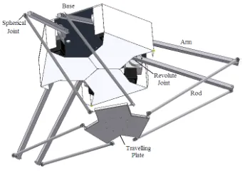
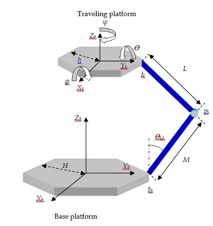
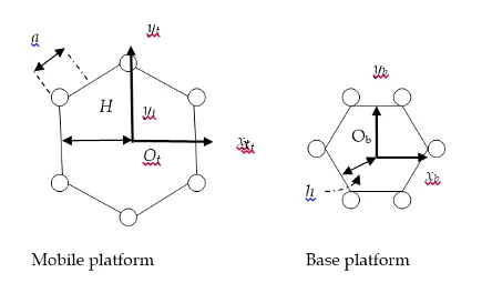
For all types of parallel robots, IKP is easily solved. Brief solution of IKP is presented in [11]. Fig. 2 shows one mechanical chain in HEXA design. In each chain, M specifies the length of the crank which is the mechanical link between the revolute and universal joints, and L indicates the length of the rod which connects universal and spherical joints. Other parameters H, h and a, are introduced as shown in Fig. 3.
The relationship between the joint angles (i=1, 2, 3 and j=1,2), the robot parameters and position and orientation of the end-effector can be obtained from the following procedure. The joint angle moves the end point of the crank of ith leg to the position pi given by:
In this equation, the joint angle is the only unknown variable. The point pi is connected to the mobile platform pivot point ti by a link with known length L, see Fig. 2.
Matrix is the rotation matrix between the base frame {bs} and a reference frame constructed in the actuated R joint, with X-axis along the joint axis and the Z-axis along the direction of the first link corresponding to a zero joint angle (see Fig. 2).
Matrix R(X, θi,j) is the rotation matrix corresponding to a rotation about X axis by the angle θi,j:
In each chain, a loop closure formulation can be adopted as follows (see Fig. 2):
Where
By substitution of cos(θi,j) = (1 − t2)/(1+ t2) and sin(θi,j) = 2t/(1 + t2) in the above equations, where t=tan(θi,j /2), it is possible to solve (3), (4), (5), for θi,j:
where
And [λi,j ρi,j µi,j 1]T is the position vector of the pivot point ti in the reference frame constructed in the actuated R joint [2].
The joint angle θi,j is variable and measured; the lengths L and M of the “base” and “top” limbs of each chain are constant; the angles of all other joints are variable but not measured.
Note that the joint between L and M is two degrees of freedom universal joint, so that the link L does not necessarily lie in the plane of the figure. To reduce the performance errors in parallel robots, its dimensions should be precisely taken into account when fabricating.
Any deviation in the position or orientation of any motor in the base produces sensible error in performance at the end-effector. Base, end-effector, arms and rods are first drawn and assembled in CAD software to make sure production precision. Based on the designed parameters in the CAD software. The ideal design lengths of the robot are given in Tables 1 to 3 in their corresponding columns.
Table 1 – Geometric parameters of the Hexa base platform
| Travelling Platform | Designed Length (mm) | Calculated Length Based on Calibration Procedure (mm) |
| h1 | 132 | 128.2 |
| h2 | 267 | 260.4 |
| h3 | 132 | 137.5 |
| h4 | 267 | 269.2 |
| h5 | 132 | 128.2 |
| h6 | 267 | 261.1 |
Table 2 – Geometric parameters of the Hexa base platform
| Name | Design Length(mm) | alculated Length Based on Calibration Procedure |
| H1 | 267 | 266.8 |
| H2 | 365 | 367.2 |
| H3 | 267 | 264.4 |
| H4 | 365 | 365.6 |
| H5 | 267 | 271.2 |
| H6 | 365 | 362.1 |
Table 3 – Geometric parameters of the Hexa base platform
| part | Designed Length (mm) | Calculated Length Based on Calibration Procedure |
| L1 | 690 | 698.1 |
| L2 | 690 | 698.1 |
| L3 | 690 | 696.5 |
| L4 | 690 | 695.0 |
| L5 | 690 | 698.1 |
| L6 | 690 | 698.1 |
| M1 | 860 | 857.8 |
| M2 | 860 | 855.0 |
| M3 | 860 | 855.0 |
| M4 | 860 | 865.0 |
| M5 | 860 | 855.0 |
| M6 | 860 | 854.9 |
Calibration Of the Robot
Since there is no way to exactly install all the joints in the designed positions and manufacture all the dimensions as perfectly as possible, the robot should be calibrated to decrease the internal uncertainties.
Calibration tunes the kinematic parameters in a manner to make the model and the real robot as close as possible. In our previous work, an image processing method of calibration was chosen in which the end-effector position and orientation were calculated from captured frames by the camera. The details could be found in [17]. In tables 1 to 3 the designed lengths and the corresponding calibrated lengths are given.
Fuzzy-Pid Control Of the Robot
Although PID controller is still a popular and inexpensive method in controlling industrial robots, scientists and engineers seek for more flexible methods that guarantee exponential stability (where PID controllers are guaranteed to be just bounded stable and need to be tuned for any new trajectory).
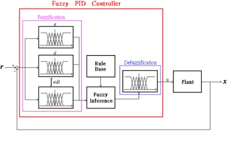
One of the controllers that guarantees convergence of error to zero is fuzzy PID (Fig. 6) which has advantages of both PID and fuzzy methods and neither of their shortcomings [20].
The basic structure of PID controller is first described in the following equations [20]:
Where q is real position and qd is desired position, conventional PID control is a sum of three different control actions. The proportional gain KP, integral gain KI, and derivative gain KD, which represent the strengths of different control action. The general structure of fuzzy logic control is represented in fig. 4 and comprises three principal components [20]:
1) Fuzzification: The process of generating membership values for a fuzzy variable using membership functions is Fuzzification. This converts main input data into suitable linguistic values. As shown in Fig. 4, there are two inputs to the controller: error and changing rate of the error signals. The error is defined as:
And the Rate of the error is defined as follows:
Where qd is the reference input, q is the output, e is the error signal, and is the rate of error. The input and output membership functions of the fuzzy self-tuning are shown in the Fig. 5.
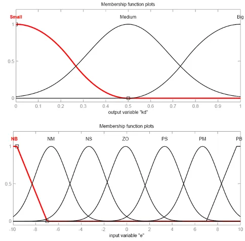
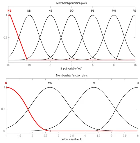
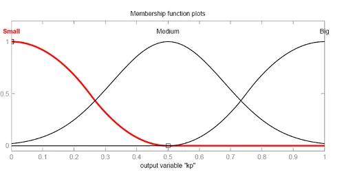
The inputs of the Fuzzy PID controller are calculated for the following variables:
1. Error input = current error – previous error
2. Delta error input = current delta error – previous delta error
The linguistic variables were defined in rule bases are:
P = positive
PB = positive big
PM = positive medium
PS = positive small
N = negative
NB = negative big
NM = negative medium
NS = negative small
NZ = negative zero
Z = zero
2) Rule base: A decision making logic which is, simulating a human decision process, inters fuzzy control action from the knowledge of the control rules and linguistic variable definitions.
Tables 4 illustrates the rule bases that used for determining KI, (there are similar tables for KP and KD) these role bases are uses to self-tuning PID controller [5].
3) Defuzzification: This yields a non-fuzzy control action from inferred fuzzy control action. Weighted-average area is the most popular method uses for defuzzification [5].
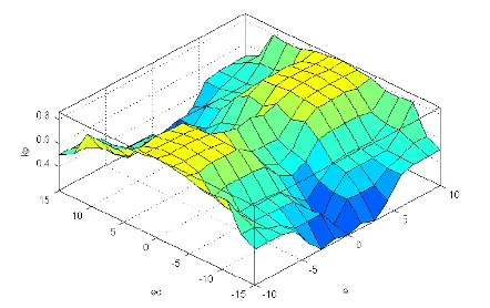
Fig. 6 shows the control surface viewer which is used to display the dependency to the other, it generates and plots an output surface map for the system.
Table 4 – rule bases for determining KI
| e/e | NB | NM | NS | ZE | PS | PM | PB |
| PB | ZE | PS | PM | PB | PB | PB | PB |
| PM | NS | ZE | PS | PM | PB | PB | PB |
| PS | NM | NS | ZE | PS | PM | PB | PB |
| ZE | NB | NM | NS | ZE | PS | PM | PB |
| NS | NB | NB | NM | NS | ZE | PS | PM |
| NM | NB | NB | NB | NM | NS | ZE | PS |
| NM | NB | NB | NB | NB | NM | NS | ZE |
A. Experimental implementation of the Fuzzy-PID controller on the Hexa robot
Several distinct trajectories have been used for Fuzzy-PID control test considering the workspace of the Hexa parallel robot and its hardware restrictions (the results of two of them will be presented here).
These two trajectories which cover the whole workspace of the robot are shown by the following equations:
Trajectory 1 (Circulatory trajectory):
Trajectory 2 (Oscillatory trajectory):
The Fuzzy self-tuning of a PID controller was designed and implemented in Hexa parallel robot. The inputs of the controller are the error of the joint angles and their derivatives and the outputs are PID gains. The system is a Sugeno fuzzy system method and weighted-average defuzzification.
Fig. 9 shows the result of implementing fuzzy PID control for Hexa parallel robot in each joint angles in the first trajectory. It can be seen that the error between desired angles and real angles is low in all six joints. Table 5 shows the minimum square error (MSE) and maximum absolute error (Mae) in robot movement in the second trajectory.
A comparison between the results of fuzzy-PID and PID control is presented in Table 6. As it can be observed from Table 6 the MSE errors of the robot with fuzzy-PID control are generally decreased in compare with the results of PID control.
A comparison between the results before and after calibration is presented in Table 7. As it can be observed from Table 7 that the position errors of the robot after calibration are generally decreased by approximately 30% in compare with the results before calibration.
Table 5 – MSE and MAE of joint angles in robot movement (trajectory 2)
| Error | Q1 | Q2 | Q3 | Q4 | Q5 | Q6 |
| MSE | 1.6368 | 1.4692 | 1.5071 | 1.5603 | 1.6068 | 1.6215 |
| MAE | 2.4554 | 2.2544 | 2.2766 | 2.6953 | 2.3593 | 2.2792 |
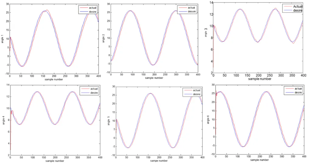
Table 6 – MSE of joint angles in robot movement with Fuzzy-PID control and PID control (trajectory 2)
| Error | Q1 | Q2 | Q3 | Q4 | Q5 | Q6 | |
| Fuzzy-PID | MSE | 1.6368 | 1.4692 | 1.5071 | 1.5603 | 1.6068 | 1.6215 |
| PID | MSE | 3.2554 | 2.345 | 3.6578 | 1.6575 | 2.4336 | 4.5635 |
Table 7- Comparison between errors in position and orientation of the mobile platform for second trajectory before and after calibration (in millimeters and degrees for positions and orientations, respectively).

Conclusions
Based on the evaluated parameters, a Hexa parallel robot was designed and simulated in CAD software and finally fabricated; a mechatronic set in which the computer receives angles from encoders (fig. 5) and produce controlling commands and send them to the motors through the controller circuit.
Then the robot was calibrated by a novel image processing-based calibration method. Then we proposed to use a fuzzy-PID controller on the robot which presented a relatively small trajectory tracking error.
Fuzzy-PID controllers have the advantage that can deal with nonlinear systems and use the human operator knowledge. Here we tested it with a parallel robot system with known parameters based on calibration. In order to compare it with one classical controller, we experimented the same system controlled by PID.
PID controller has only three parameters to adjust. This controller cannot be applied with the systems which have a fast change of parameters, because it would require the change of PID constants in the time. Hexa robot Controlled system shows good results in terms of response time and precision when these parameters are well adjusted by fuzzy logic.
References
- J. P. Merlet, Parallel Robots, Kluwer Academic Publishers, 2006.
- J. E. Gwinnett, patented in 1931, US Patent No. 1,789,680.
- Gough, 1956, Contribution to discussion of papers on research in automobile stability, control and tyre performance, In: Proceedings Auto Div. Mechanical Engineering.
- D. Stewart, A Platform with 6 Degrees of Freedom, Proc. Of the Institution of mechanical engineers, 180:371-386, 1965.
- R. Clavel, 1991, DELTA, a Fast Robot with Parallel Geometry, In: 18th International Symp. On Industrial Robot, pages 91-100, 1988.
- F. Pierrot, P. Chiacccio, A. Fournier. Hexa; A Fast Parallel Robot, Journal of Robotic Systems, Desamber, 1991.
- F. Pierrot, P. Dauchez, M. Uchiyama, K. Iimura, K. Unno, O. Toyama, 1992, HEXA: a Fully-Parallel 6-DOF Japanese-French robot, Proceedings of 1st Japanese-French Congress of Mechatronics, Besancon, France.
- M. Uchiyama, K. Iimura, F. Pierrot, K. Unno, O. Toyama, Development of a 6-DOF High-Speed Parallel Robot Hexa, 10th annual Conference of the Robotics Society of Japan, 1992.
- P. Maurine, D. Liu, M. Uchiyama, Self Calibration of a New Hexa Parallel Robot, 1998.
- M. Uchiyama, K. Masukawa, T. Sadotomo 1994. Experiments on Dynamic Control of a HEXA-TYPE Parallel Robot, Intelligent Automation and Soft Computing. Proceedings of the First World Automation Congress, WAC ‘94, August 14- 17, Maui, Hawaii, U.S.A. TSI Press, 2, 281-286.
- P. Last, J. Hesselbach, N. Plitea, An Extended Inverse Kinematic Model of the Hexa-Parallel-Robot for Calibration Purposes, Proceedings of the International Conf. on Mechatronics & Automation Niagara Falls, Canada, July, 2005.
- P. Last, C. Budde, C. Bier, J. Hesselbach, Hexa-Parallel-Structure Calibration by Means of Angular Passive Joint Sensors, Proceedings of the International Conf. on Mechatronics & Automation Niagara Falls, Canada, July, 2005.
- J. Hesselbach, C. Bier, A. Campos, H. Lowe, Direct Kinematic Singularity Detection of a Hexa Parallel Robot, Proceedings International Conf. on Robotics and Automation Barcelona, Spain, April, 2005.
- M. Ahmadi, MSc. Thesis, Design, Fabrication and Robust-Adaptive Control of a Hexa Parallel Robot, Shiraz Unviersity, Dept of Mechanical Eng. 2009.
- M. Ahmadi, M. Dehghani, M. Eghtesad, A. Khayatian, Inverse Dynamics of Hexa Parallel Robot Using Lagrangian Dynamics Formulation, Feb. 2008, WAC 2009.
- M. Dehghani, M. Ahmadi, A. Khayatian, M. Eghtesad, Neural Network Solution for Forward Kinematics Problem of Hexa Parallel Robot, American Control Conference, June, 2008, Seattle, Washington, USA.
- M. Dehghani, M. Ahmadi, A. Khayatian, M. Eghtesad, Wavelet Based Neural Network Solution for Forward Kinematics Problem of Hexa Parallel Robot, INES, Feb. 2008, Miami, FL, USA.
- M. Dehghani, MSc. Thesis, Calibration of a Hexa Parallel Robot, Shiraz Unviersity, Dept of Electrical Eng. 2009.
- F. L. Lewis, C. T. Abdallah, D. M. Dawson, Control of Robot Manipulators, ISBN 0-02-370501 -9.
- T., K.S. , K. F. Man ; G. Chen, S.m Kwong, An optimal fuzzy PID controller, Industrial Electronics, IEEE, Volume:48 Issue:4, 2014
